The current can be represented as a transient DC component added on top of a symmetrical AC component. The type of conductor copper or aluminum.

Calculate the short-circuit current at the secondary of the transformer.
How to calculate fault current 3 phase. Welcome to schneider electrics fault current calculator. Please select system type from these two. Single Phase with Cable Run.
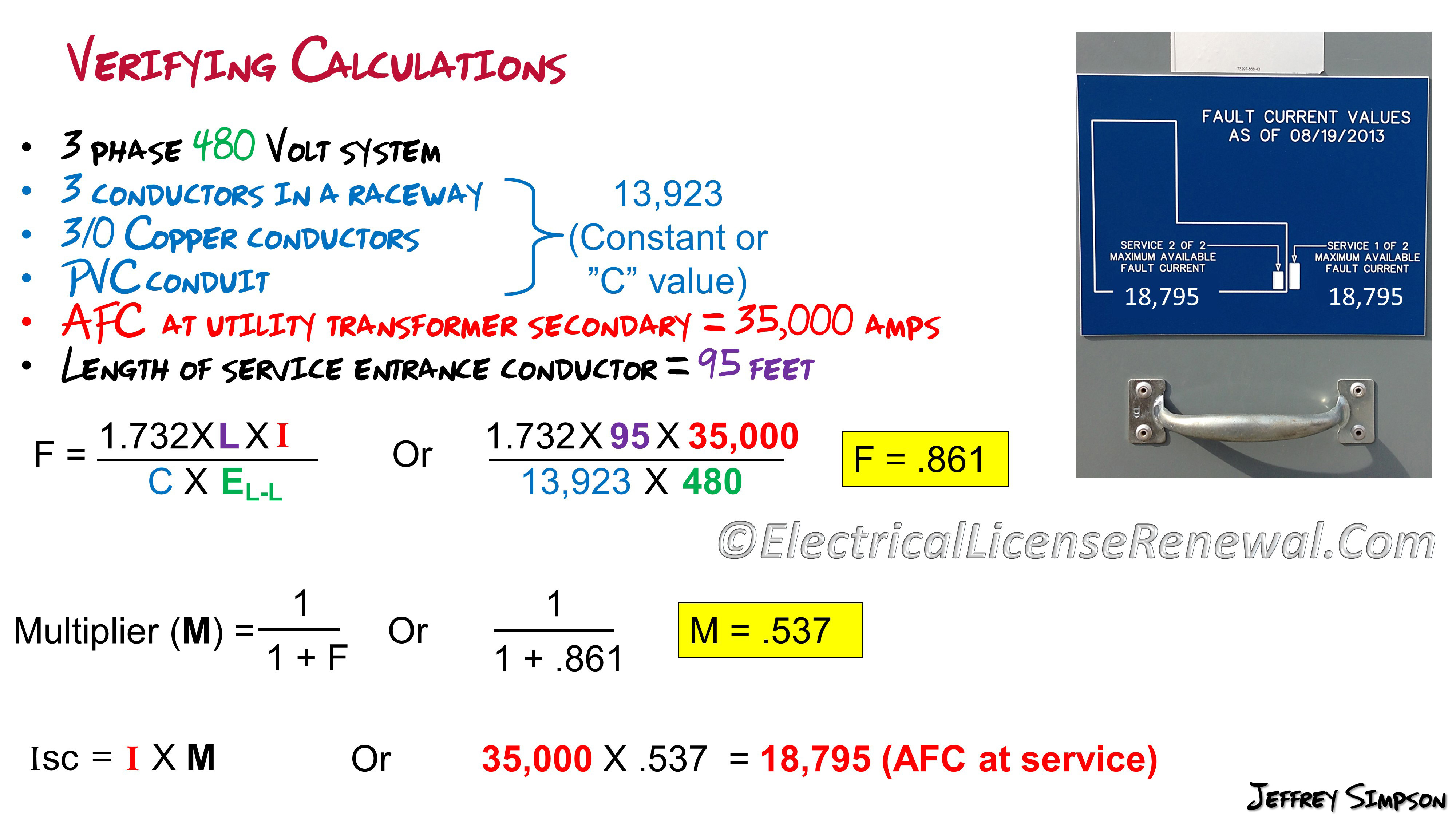
Three Phase Fault In a three phase fault all three phases L1 L2 and L3 are shorted together. To find the fault current at any point in the network a sum is made of the impedances in the network between the source of supply including the source impedance and the. Below is a 3-step formula to calculate three-phase AFC also called the available short circuit current ISC at the end of a run of wire.
In order to use the calculation several factors must be known. The length of conductor. The amount of AFC where the conductor originates.
The size of the conductor. The type of conductor copper or aluminum. The power taken by a circuit single or three phase is measured in watts W or kW.
The product of the voltage and current is the apparent power and measured in VA or kVA. The relationship between kVA and kW is the power factor pf. KW kVA x pf.
3-Phase fault current transients in synchronous generators When a symmetrical 3-phase fault occurs at the terminals of a synchronous generator the resulting current flow in the phases of the generator appear as shown. The current can be represented as a transient DC component added on top of a symmetrical AC component. Three-phase short-circuit current Isc calculation at any point within a LV installation using impedance method Calculation of Isc by the impedance method In a 3-phase installation Isc at any point is given by.
Where V 20 line-to- line voltage corresponds to the transformer no-load voltage which. 16 Calculation of the ground-fault current in a network with isolated neutral To answer the am. Core question How is the current path of the earth fault current closed while looking at the return part of the current loop from ground into the elsewhere highly.
Current at the point of fault. Add motor contribution if applicable. Procedure for Second Transformer in System Step A.
Calculate the f factor ISC. Calculate the short-circuit current at the secondary of the transformer. See Note under Step 3 of Basic Point-to-Point Calculation Procedure.
IpefcUoc Ze 24m of R1R2 I hope I am right. Ps I edited step c adding 3-phase to sub-board is because a 3-phase fault will give you the highest fault current at the board. If the sub-board is only a single phase board IpsccUoc Ze24m of R1Rneutral for a TNC-S supply.
Transformer short circuit fault current. I fault S kVA x 100 1732 x V V x Z. The Z will lie between 4 to 10.
A transformers nameplate details are 25 kVA 440V secondary voltage 5 of percentage impedance calculate the short circuit fault current. I fault 25 x 100 1732 x 440 x 5 I fault 066 kA. The third experiment proves the relation between the earth fault current and current via the resistor and the currents via the healthy phases whereby it is shown that the fault current is equal to the root square summation of currents of resistor and healthy phases.
When calculating Fault Loop Impedance Select the Correct Transformer Type Above. Three Phase Transformers Divide the Values for Vs secondary Voltage by 3 and the VA by 3. For Centre Tapped to Earth C TE transformers halve the values for Vs and VA.
For RLV 110V C TE Disconnection Times Zs figures refer to BS 76712008 4118 Table 416. Fault current calculationhttpsyoutubez2GeCFauMY8 About Press Copyright Contact us Creators Advertise Developers Terms Privacy Policy Safety How YouTube works Test new features 2021. The approximate three phase fault current is given 240Z.
Therefore to determine the three phase fault current from a single phase measurement we take the ratio of these two ie. 240Z divided by 2402Z which equals 2. Apologies for using the old voltage levels.
Eawr89 Mar 21 2006. Calculate the short-circuit current at the secondary of the transformer. See Note under Step 3 of Basic Point-to-Point Calculation Procedure Note 5.
The L-N fault current is higher than the L-L fault current at the secondary terminals of a single-phase center-tapped transformer. The short-circuit current available. This quick calculation can help you determine the fault current on the secondary of a transformer for the purpose of selecting the correct overcurrent protective devices that can interrupt the available fault current.
Fault Current Full Load Amps Impedance Z Example. Calculate the maximum fault current for a transformer rated 138kV-480Y277V 1000kVA 575Z Step 1. This must be real number ex230 or 125.
End of Run Fault Level Icc Voltage Drop Vd Impendance Of the Cable Zc Supply Impedance Zs Resistance of the Cable Rc Reactance Of.